
The ubiquity of the electric multi-rotor drone was made possible by Arduino based flight software and Linux based ground station planning software. Some drone manufacturers like 3D Robotics and Yuneec have stayed true to the Open Source Software roots while the industry leader DJI is predominantly closed source and proprietary.
Multi-rotor Configurations:
- Tricopter: three motors/three arms
- Quadcopter: four motors/four arms
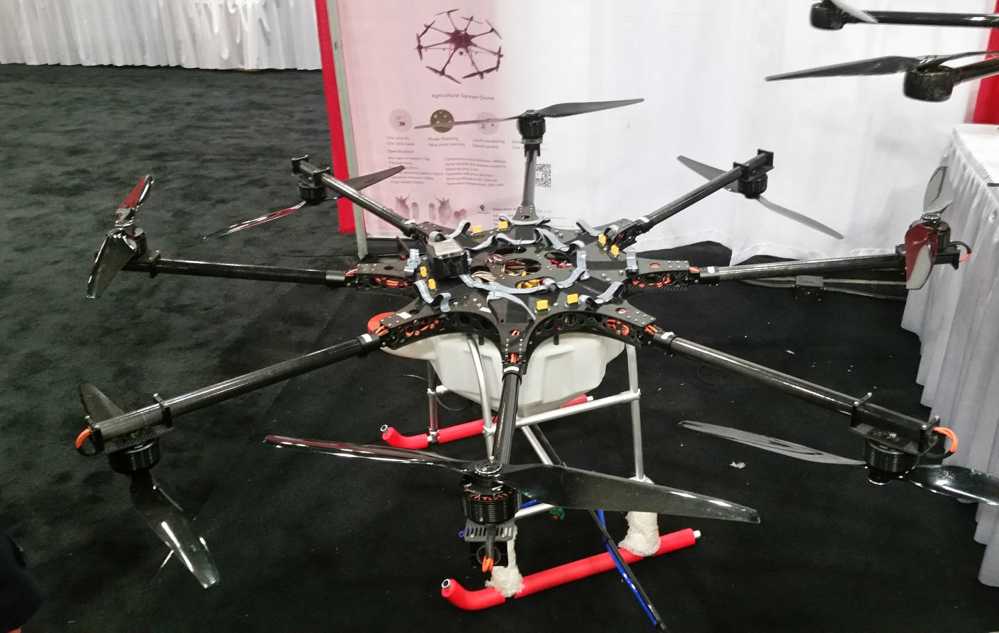
- Hexacopter: six motors/six arms
- Octacopter: eight motors/eight arms
- Y6: two motors on each of three arms
- X8: two motors on each of four arms
This page lists the open source software components and related hardware to support the drone ecosystem.
FOSS Based Drone Manufacturers:
- 3D Robotics - Site Scan, IRIS+ and Solo quad-copter video drones (DroneKit)
- Yuneec - quad-copter video drones (PX4/DroneCode)
- Intel Aero - development drone using Intel components
- jDrones - catapult launched unmanned aircraft
- Squadrone System: Hexo+ - video hexo-copter (kickstarter)
- Walkera - video (telephoto) and racing drones
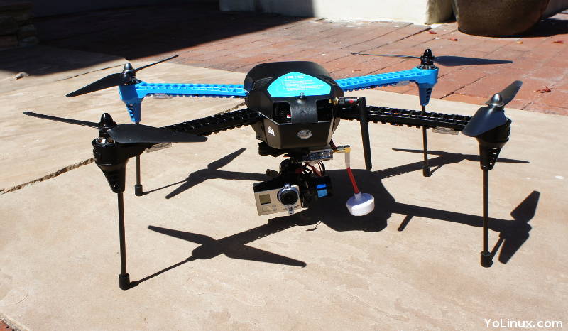
Three-Dimension Robotics (3DR) IRIS+ video drone based on Open Source Software, Pixhawk flight controller and a GoPro video camera
The flight software is the software resident on the drone itself. At a bare minimum it typically can autonomously follow a flight plan or take inputs from a remote control transmitter. Either source of control input is processed by the flight software to send the appropriate signals to the Electronic Speed Controllers (ESC) which control the speed of the electric motors. Calculations often involve using Inertial Measurement Unit (IMU), Global Position Satellite (GPS) position, altitude (barometric altimeter) and compass bearing (magnetometer) to improve position awareness and position stability. GPS supports hands off drone position keeping "Loiter Mode" (lat/lon and altitude hold) and "return to launch" (RTL), a failsafe that automatically returns the drone to its launch point. Of course this is only useful as an outdoor feature which requires a clear view of the sky and satellite signals. PX4 and APM are the two leading open source candidates for flight control software.
Flight control software has evolved beyond basic flight to include a suite of tools to support flight including mission planning software, mobile apps, autonomous operation, collision avoidance, telemetry processing, cameras and sensors support and applications for many esoteric functions. The software applications are all expected to interface with one another and operate together seamlessly. This collection of interoperable drone applications is called the "Drone software Stack".
Big open source institutions like the Linux Foundation (industry financed) are sponsoring flight software operating systems through the DroneCode project. Industry partners include chip makers like Intel and Qualcomm as well as by FOSS based drone manufacturers. Development and experimentation has begun using more powerful Linux based Raspberry Pi controllers. There are even "fused" flight controller systems that have integrated a Linux based compute node with a real-time Arduino based flight control on a Pixhawk based companion processor. These systems are running a Linux computer (Yocto real-time Linux, Raspberry Pi, etc with an ROS layer and libraries) with a "Companion Computer" (CC) for real-time flight control. Flight software follows drone brands and flight controller brands where legacy 3DR and partners are ArduPilot based, DJI is mostly proprietary but has new projects based on Robot Operating System (ROS) and Libre Pilot based systems are simpler and used extensively in smaller drone racers.
Drone Software Stacks:
Most provide a software technology stack which includes a flight control/autopilot, an SDK, ground software, mobile apps, etc:- DroneCode.org: (stack) (Linux Foundation sponsored) (Linux Foundation sponsored)
- PX4 flight code project (originated from the Pixhawk flight controller project). Runs on QuRT OS, Pixhawk-compatible flight controllers and Linux based systems.
- Flybase.com: FlytOS: (stack) Drone OS which supports PX4 or APM, multiple companion computers built on ROS and Linux, a control station, etc.
- dRonin.org - open source software stack targeted to FPV racing
- DroneKit.io - 3DR Solo drone stack which includes Yocto Linux connected to a Pixhawk/ArduPilot autopilot and MAVLink telemetry all connected to an Android based ground software and their cloud services.
- PaparazziUAV.org - autopilot and ground station software
- NVidia Redtail - autonomous (ROS based) navigation and deep learning platform for the NVIDIA Jetson embedded platform + Pixhawk
- FPV Drone Racing: (basic flight control)
- Libre Pilot (OpenPilot) - (source)
- CC3D flight computer
- Clearflight: typically works by itself. Configuration GUI is a Chrome browser app/plugin.
- Clearflight Github
- Seriously Pro - flight computer for Clearflight
- Libre Pilot (OpenPilot) - (source)
Flight Controller/AutoPilot:
These are the flight/auto pilot software found in many drone stacks. This is the real-time flight control software and the operating core of the flight software.- PX4: (large number of peripherals supported)
- PX4 flight code project (originated from the Pixhawk flight controller project). Runs on QuRT OS, Pixhawk-compatible flight controllers and Linux based systems.
Note that NuttX based platforms are embedded, minimalist Real-Time OS (RTOS) platforms. - APM: also known as ArduPilot (large community and used in 3DR Solo)
- ArduPilot.co.uk: APM - drone stack based on Free open source autopilot firmware (PX4/APM) that supports planes, multi-copters, ... Runs on APM hardware.
- ArduPilot.org: APM - Ardupilot software for Pixhawk 2 hardware. This hardware was originally developed by 3D Robotics.
The flight controller software in turn runs on a Real-Time Operating System (RTOS): (typically bundled with the flight stack)
- NuttX - POSIX/ANSI PX4
- PX4 Nuttx - NuttX with patches for PX4
- Arduino + AP Hardware Abstraction Layer
- ROS (Robot Operating System) not a true RTOS but a messaging and middle-ware layer and support applications which runs on a POSIX compliant OS such as Linux, designated for high-end functionality, typically on a "Companion Computer".
Support Software:
- MAVLink - message marshaling library for drones - used for telemetry streams, camera gimbal control, configuring the on-board mission or changing the system configuration.
- ROS.org: DJI SDK (Github: DJI OSD source code) - a ROS interface for the DJI SDK using a serial port.
- MW OSD - On Screen Display Open Source solution for use primarily with UAV's and with GPS. Supports APM and Naza flight controller hardware.
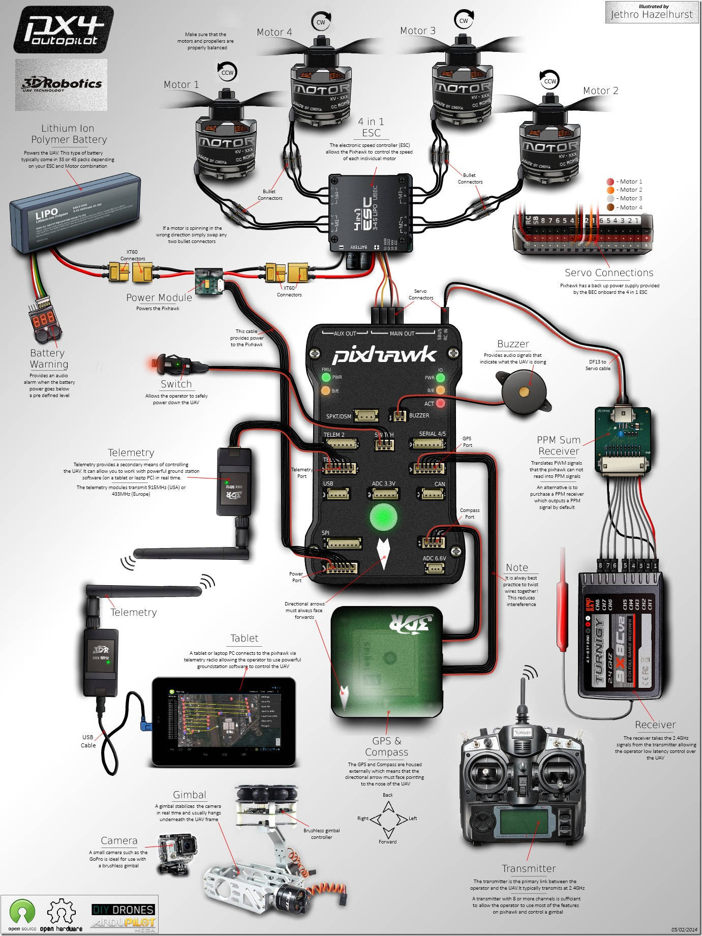
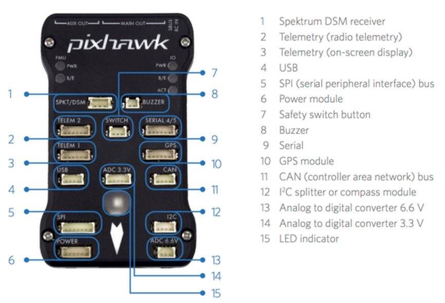
Each drone will have a flight controller which is comprised of a computer with an Inertial Measurement Unit (IMU). The IMU measures the drone's orientation and movements. Thrust adjustments are calculated based on the gyroscopic and accelerometer measurements. Most Open Source flight software runs on an Arduino based flight controllers. An industry standard was developed by 3D Robotics known as the Pixhawk. This runs a single purpose embedded OS.
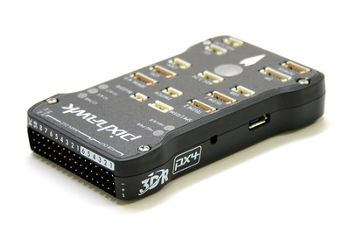
- Pixhawk - integrates with a wide array of sensor inputs. Uses Dronecode software stack. Can use either PX4 or APM.
- Libre Pilot CC3D: simple flight computer based on ARM chip, popular in the FPV racing
- OcPoC (Octagonal Pilot on Chip) + Xilinx Zynq - SoC FPGA-based open-source flight control platform, runs ArduPilot/APM or PX4
(ready to fly development platform) - Qualcomm Snapdragon Flight - multi-core ARM processor, Hexagon DSP, WiFi, Bluetooth, global navigation satellite system (GNSS), video processing.
- Intrinsync.com - ready to use compute modules
- Intel® Aero Ready to Fly Drone - development platform uses Intel Aero Compute Board, Intel RealSense depth and vision running embedded Linux (Yocto) and PX4 autopilot
- DJI: Naza-M V2 - includes an inner damping 3-axis gyro, 3-axis accelerometer and barometer.
- Seppuku - processor for dRonin based FPV racing
- Tau Labs: Sparky 2 - controller for use with Libre Pilot software stack
- RobSense - runs their own open source variant of the ArduPilot flight control stack and their own RTOS (PhenOS) [all on github]
- Qualcomm: Snapdragon Flight - supports Linaro Linux (ARM based), OpenCV (Open Source Computer Vision Library) and existing drone software
- Intel: Aero - compute board based on quad core Atom processor running Yocto Linux. Connect with micro-HDMI and USB ports
Software: Intel Aero software, Flybase.com: FlytOS. - Emlid.com: Navio2 - Autopilot HAT (Hardware Attached on Top or add-on board) for Raspberry Pi for use with ArduPilot and ROS/Linux
- Erle Robotics: PXFmini - connects to the Raspberry Pi Zero to run APM software stack
- NVidia Jetson TX1/2 - Companion computer with NVidia GPUs running Linux.
- Hardkernel.com: ODROID - ARM based single board computer (SBC)
Electronic Speed Controllers (ESC) are essentially the electronic throttle control for the motors controlled by inputs from the flight controller. Multi-rotor drones typically use fixed pitch propellers thus thrust adjustments are made by changes in RPM (as opposed to helicopters which run at a constant RPM but change the propeller pitch to change thrust). When drones are flying, the flight control computer calculates what RPMs and power to deliver to the motors based on stability and control needs as well as from operator or flight plan inputs. The ESC acts like a digital variable relay, taking power from the battery and input signals from the real time flight computer (typically the Pixhawk) via a signal/servo connector (three wire: Signal, 5 volt power and ground). When directed to give a motor more "throttle", it directs a change in the frequency of the pulses to the motor to change the RPMs. This is a Pulse Width Modulated (PWM signal) that changes the RMS voltage to the motors. This is vastly different from brushed motors which increased their RPM when more voltage is applied. Flight systems can be designed with one ESC per motor or as an integrated module for all motors (4in1 ESC:common for quadcopters).
The ECS's are rated for the power they can deliver to a motor (eg 10 Amp, 20 Amp or 40 Amp) and for its BEC or "Battery Elimination Circuit" (if there is one). Note that is is best not to have multiple BEC's involved on the same circuit as they can interfere with each other. An ESC without a BEC is often referred to as an OPTO or optoisolator. The BEC rating is for its ability to output a constant voltage if the ESC is used to deliver power to the flight control computer, RC receiver or servos. Of course the total power draw from the motors and anything else the ESC is powering, can not exceed the rated power of the ESC.
The ESC connectors are typically a servo connector at one end which connects to the flight controller and 5mm bullet connectors (or wire to solder) to the motors. There is an additional connector (typically XT60) to the battery or power module also known as a power distribution board (PDB).
Programming kits (hardware interface module with a USB connection to your desktop computer) are available to program the ESC settings: low-voltage cutoff, prop brake strength, governor gain, torque limits, etc. The low voltage cutoff setting is required when using LiPO batteries to avoid drawing down the battery below acceptable limits.
- Castle Creations
- E-Flite
- ElectriFly
- HiTec - 12 to 60 amp
- Lumenier
- Turnigy
A Universal BEC (UBEC) is used when an ESC doesn't have a built-in BEC. The UBEC is connected directly to the main battery and is usually more power efficient and less prone to overheat than an ESC/BEC.
Programming kits are available to program the ESC settings: low-voltage cutoff, prop brake strength, governor gain, torque limits, etc. Some have an auto-calculate feature that assumes the LiPO battery type based on the battery voltage. eg. If the voltage is between 8.8V to 17.6V, it is judged as a 4s Lipo.
Programmable features include:
- The low voltage cutoff threshold setting is required when using LiPO batteries to avoid drawing down the battery below acceptable limits.
- Governor Gain: setting the sensitivity of the ESC at maintaining RPM. Small light drones may want less sensitivity to avoid user over-controlling the vehicle. Throttle sensitivity.
- Drag Brake Force: simulates a brushed motor where it slows down when you let off the throttle. More useful for RC cars than drones.
- Start Mode(Punch): speed from the start of full throttle. Makes a drone more manageable for a beginner who might be prone to use excessive throttle. More useful for RC cars than drones. Acts as traction control by limiting full power.
- Max Brake Force: brakes the RPM down when the throttle goes down. Without this the motor is braked by the air resistance of the propeller.
- Over-heat Protection: protects the ESC from overheating
Typically the ESC vendors have ESC programming cards for their particular ESCs.
- Hobby King - good source for ESC programming cards for each vendor
- Thunder Tiger
- Castle Link: USB programming kit
- Durafly
The Power Distribution Board (PDB) isolates and connects the battery to all of the ESC's. The PDB acts as a power junction box with a voltage regulator to maintain a constant voltage. Typically a LiPO battery may output over 14 volts but the ESC's connecting to the PDB will receive 12 volts. LED lights and other electronics may receive 5 volts from a second voltage regulator on the PDB. The draw of all of the ESC's can not exceed the capacity rating of the PDB. For example 4 x 10Amp ESC's require a PDB rated at 40 Amps. When building a system, one must match the battery (number of cells which determine voltage), the PDB (to accept the voltage), the ESC's power load capacity and the motor power draw so that no component is overloaded beyond its' capacity.
- Matek Systems
- Lumenier
- Spektrum 5V/12V
- 3DR Power Module - power to Pixhawk
Telemetry, or the transmission of drone data such as location (lat/lon/altitude), battery voltage, orientation, signal strength (RSSi) feedback, etc is an important part of the drone ecosystem. The profile of battery use of each flight is different. Loiter control on windy days, hover vs travel, camera gimbal use, cold days vs warm, etc will all create a different battery consumption profile. Thus it is essential that the pilot be aware of the battery voltage in order to be aware of how much time remains in the flight. The signal strength, or RSSi, lets the pilot know when one is flying beyond the range limit of their radio transmitter. This is all handled by the telemetry system. Typically the flight computer will have a telemetry port which will connect to a separate transmitter/receiver (915 MHz USA or 433 MHz Europe) which communicates with a separate receiver and antenna mounted on the transmitter which will then display this information on the transmitter front panel. The transmitter is used to transmit telemetry data and the receiver can be used for "follow me" mode. It is also quite typical to run ground station software on a computer, tablet or phone with a telemetry transmitter/receiver connected via USB in order to display drone information including flight location on a map.
Follow mode is enabled by using a phone app which transmits the person's GPS lat/lon/altitude to the drone so that drone can use it's GPS to calculate where to fly and where to point the camera. The USB connected transmitter/receiver is used to make this data connection. Follow mode often has various modes including follow in front, behind or from either side.
Typically telemetry is handled by the flight control software using the MAVLink publish-subscribe marshaling library.
Telemetry Vendors:
- FrSky DJT - receiver
- FrSky sensors
- HiTec RC
- Graupner
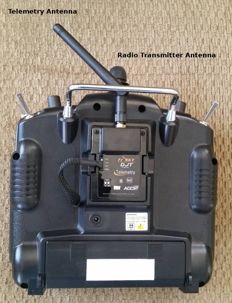
Telemetry receiver on the back side of the flight control transmitter. Telemetry data display is on front panel.
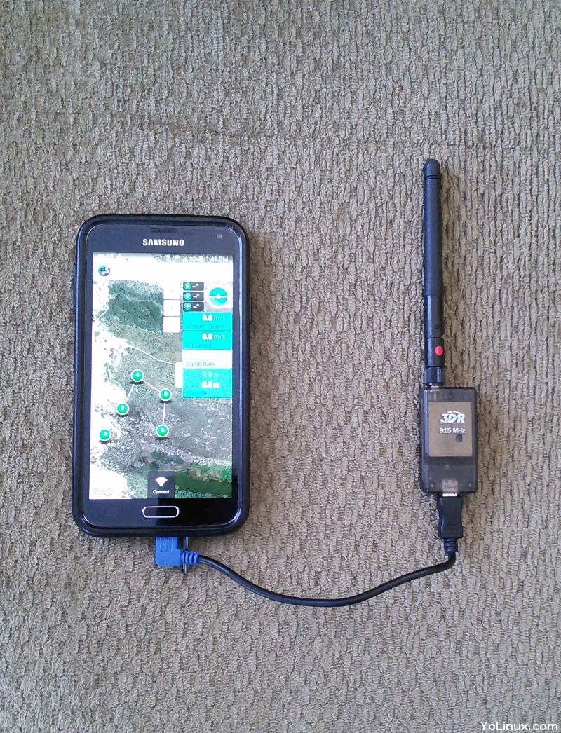
Telemetry displayed by Droid Planner app. Can also transmit phone's GPS coordinates and altitude to drone to support follow mode.
Automated outdoor flight relies on the Global Navigation Satellite System (GNSS), a worldwide, international system of satellites (GPS, GLONASS, Galileo, Beidou) or colloquially known as Global Positioning System (GPS) for the original US provided constellation of 32 global satellites. Miniaturization has been effective at placing a complete GNSS receiver on a chip (eg: ublox). Some chips even include Inertial Navigation Systems (INS) as a primary navigation unit with corrections from GNSS where the INS accelerometers provide an accurate solution but only for a short period of time. The benefit of a GNSS/INS system is that the INS can provide position and angle updates at a quicker rate than GPS. These systems often provide a 3-axis compass and/or barometric altimeter as well.
The GNSS unit will connect to the flight controller using one of the following protocols over a USB-UART serial connection:
- UAVCAN (CAN bus): a publish/subscribe network which can be used on real-time systems. UAVCAN uses a "democratic network" (no master node like 1553). The standard messages conform to the "Data Structure Description Language" (DSDL) standard. For more information see UAVCAN.org.
- NMEA 0183: Combined electrical and data specification for marine electronics (GPS, anemometer, gyrocompass, autopilot, etc).
GPS/GNSS/Inertial Nav vendors:
- Applanix: Trimble - precision GNSS-Inertial Board Set plus Inertial Measurement Unit (IMU) for mapping drones
- Hex Aero - Pixhawk compatible
- Radiolink
- SBG: Ekinox INS/GPS - combines an Inertial Measurement Unit (IMU), runs an enhanced on-board Extended Kalman Filter (EKF) which fuses in real-time inertial data with internal GNSS information. All-in-one INS/GNSS solution. Survey Grade GNSS receiver.
- Sparkfun Electronics - GPS receivers, antennas, loggers
- USGlobalsat
- Zubax - GPS/GLONASS receiver, a high-precision barometric altimeter, and a 3-axis compass with thermal compensation.
PC Based:
- Mission Planner - C# (.cs files) on .net (MS/Windows) or mono (OSX, Linux) platforms
- APM Planner - APM Planner Ground Control Station (Qt). Uses MAVlink. Configure APM or PX4. Supports autonomous flight planning.
- QGroundControl (QGC) - full flight control and mission planning for any MAVLink enabled drone. Configuration for ArduPilot or PX4 Pro powered flight control. (Linux Foundation sponsored)
- Real Flight - RC flight simulator
- Skyward IO - Collaborate with customer and pilot on flight plans
Web Based:
- Flytbase: FlytConsole - configure, calibrate, monitor, command and control drones, Mission monitoring.
Hardware:
Typically this involves a laptop but there are custom ground station hardware solutions.- Chaney Aerospace: Alio - hardened case with a built-in computer and touch screen monitor.
- Chaney Aerospace: Imperium - larger pro ground station
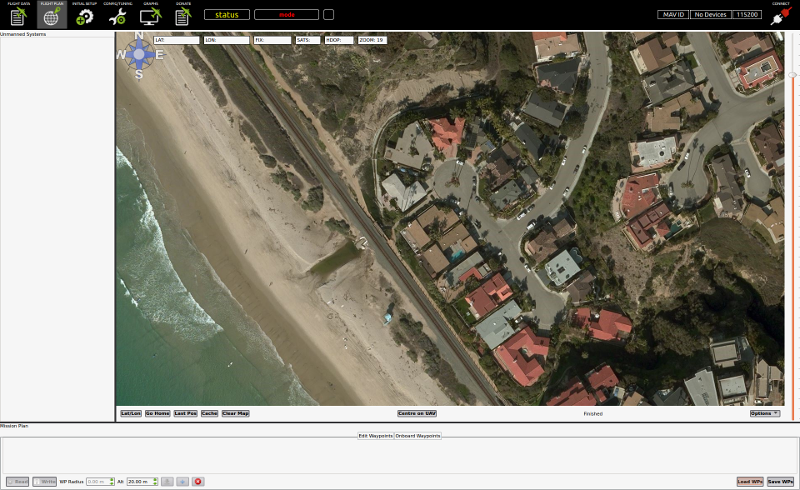
APM Planner 2.0.24
- B4UFLY - FAA mobile app to help determine whether there are any restrictions or requirements in effect at the location where they want to fly
- AirMap - Airspace maps from FAA "Know before you fly" program
- LibrePilot2Go - Android app ground station flight planner
- Drone Deploy - Capture imagery, process maps and 3D models, and interpret data
- Drone Watcher - detects, tracks and alerts most commercially-available consumer and prosumer drones and records data including the drone type and ID using advanced signals intelligence technology
- Pocket Drone Control - Get local weather and drone flight conditions for your current location
- Tower/DroidPlanner 3 - Ground Control Station (GCS) Android app built atop DroneKit-Android, for UAVs running Ardupilot software. Works with 3DR drones (default).
- UAV Forecast - identify no-fly zones, get weather forecasts, view flight restrictions
- Real Flight - RC flight simulator
- Skyward IO - collaborative flight planner
- Verify.com: on demand drone flight insurance - select flight area and get instant approval with on-the-spot proof of insurance
- AirNest - flight planning, logger, playback and metrics
- Hover - flight readiness dashboard to let you know if its safe to fly your and a real-time weather and an aggregated news feed. Includes no fly zone maps (US only)
- AZ Screen Recorder - Android screen recorder (free on Google Play)
FlytBase Apps available as source code: (only)
- Joystick - Drone control uses FlytBase Drone Navigation APIs to send velocity set-points to your drone and eventually control Roll, Pitch and Yaw movements of the vehicle.
- Video Streaming App - for drones using Wi-Fi video streaming.
- GPS Follow Me App - GPS Follow Me mobile app enables your drone to follow you around.
- Visual Follow Me - object tracking using computer vision
- AprilTag Detection - AprilTags are 2D bar codes developed for robotics applications and are now being used in various drone applications. This project integrates AprilTags detection with FlytOS.
- Obstacle Detection using Sonar - uses Sonar connected to Arduino to detect obstacles from 6 directions and publish the distance data into ROS.
- Visual Servoing - video pointing and control - This app uses gimbal APIs to control a 3-axis gimbal in order to keep the camera(mounted on gimbal) focused on an object of interest in the vicinity. FlytOS vision APIs are used to detect and track the object.
- Search and Rescue - dedicated to find missing people
Drone Software:
- DroneDeploy - drone mapping
- SkyWard - drone support software
Visible light, optical sensors (still cameras and video).
Standard Camera Sensor Formats:
Camera sensor sizes come in standard formats (larger is better):- Full Frame (FF): 35mm sensor, professional grade and "prosumer" cameras (largest standard frame size format: 36 mm x 24 mm)
- APS-C: 1.5:1 surface area vs FF (23 mm x 15 mm)
- M4/3: 2:1 surface area vs FF (smallest: 17.3 mm x 13 mm)
- One Inch: (13.2 mm x 8.8 mm)
- GoPro Hero 4: (5.37 mm x 4.04 mm)
- iPhone: (4.54 mm x 3.39 mm)
Full Frame format: the 36mm x 24mm format standard closely matches the 35 mm standard once used for film.
APS-C format: (Advanced Photo System type-C) is a smaller form factor than the 35 mm Full Frame and gathers 2.4 times less light
- Sony R10C (used on the 3DR Site Scan drone)
- Ricoh GR-2
Micro Four Thirds Cameras: also known as MFT or M4/3 is a standard design for mirror-less, interchangeable lens digital cameras and lenses. The design facilitates smaller body designs and shorter focal distances supported by smaller lenses. The image sensor is 18 mm × 13.5 mm with an imaging area of 17.3 mm × 13.0 mm using a 4:3 image aspect ratio. Typical DSLRs are 3:2 defined by the traditional 35 mm format. Cropping is used to produce 16:9, 3:2 and 1:1 ratio images. The MFT format cameras are becoming a favorite for high quality drone photography.
- Lucint Systems - designed for photogrammetry. Captures precise GPS time-stamp. Multi-spectral.
- Black Magic: Micro Cinema - supports RAW
- DJI Zenmuse X5S
- Z Cam E1
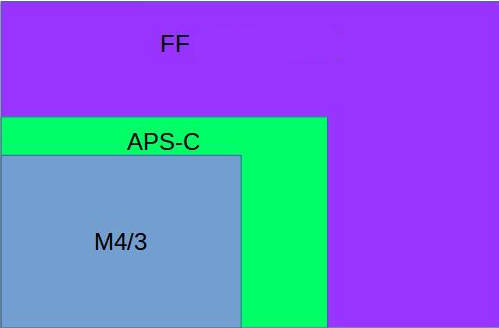
Image shows a relative size comparison of the Full Frame, APS-C and M4/3 CCD
Other:
Pro Tip: If shooting in GoPro "ProTune", Cannon "Log" (Logarithmic), Sony "S-log", Panasonic "V-log", DJI "D-log" or any "CinStyle" mode, you will find that the color is very flat. Use a video editor which can apply a LUT (Look-Up Table). This acts like an Instagram filter to add color saturation. If using DaVinci Resolve, apply the LUT known as "Rec 709" to get a familiar broadcast look. The LUT file format is typically compatible with Adobe Premier Pro, Final Cut and DaVinci.
Camera Accessories:
- RC Flysoft - RC Switch for remote digital camera control
- Snake River Prototyping - GoPro and DJI camera filters
- Polar Pro - filters and accessories
- Wooden Camera - custom mounts and accessories
- FoxFury - drone lights for night video
- Lume Cube - drone lights for night video
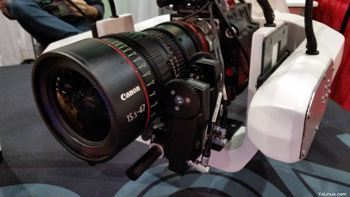
Intuitive Aerial: Aerigon with Canon camera zoom
Lidar, multi-spectral and infrared sensors: typically multi-spectral sensors are used in agricultural land management and crop assessment using green and near-infrared wavelengths. Blue wavelengths are used for atmospheric imaging. Thermal infrared imaging can also be used for crop assessment where warm areas can indicate a lack of water.
Infrared: The various degrees of heat detected by IR have no colors so the camera will assign colors where none exist. The typical IR camera supports 256 shades in its color spectrum. There are predefined color palette standards which are often used to map hot to cold ranges to a color. While IR is noted for its use at night, it is equally effective during the day. IR is also able to "see" through smoke but suspended moisture (fog) blocks IR and visible spectrum EO cameras.
- black-hot: employed by the US military where the warmest is black and the coldest appears white. Image displayed in black, white and greyscale.
- white-hot: used in search and rescue where the hottest is white and coldest is black. Image displayed in black, white and greyscale.
- Artic: white (hot) to blue (cold)
- green-hot: green (hot) to black (cold)
- InstAlert: white-hot with the hottest displayed in red.
- Grey-Red: white (cold) to red (hot)
- Other: Fusion, Rainbow, IronBow, Lava
UAV Sensor Vendors:
- Micasense - multi-spectral multi-camera arrays
- Infrared (heat):
- Ascent Systems: LWIR, IR, optical
- MapIR - Infrared. Fits GoPro gimbals and mounts.
- Vision Aerial: Helium - gimbaled infrared and visible (GoPro) wavelength camera combination
- FLIR.com: Flir Vue - Thermal Imaging Cameras for sUAS, Flir Vue uses a GoPro-compatible 10-pin mini-USB connector to feed the camera a regulated 5VDC power supply and get analog video out to your video transmitter
- Teracam - multi-spectral, infrared, multi-camera arrays
- CjlTech: IR4 - Infrared floodlight illuminator
- Lidar:
- Headwall Photonics - hyper-spectral and LiDAR sensors integrated with GPS/IMU geo-referencing
- Velodyne LiDAR - used by Google on their street-view cars (Puck)
- Phoenix LiDAR - Laser Radar, 3D Laser mapping, sensitive enough to detect small guy-wires. Geo-referenced data. Optional IMU and dual GPS
- LiDAR USA
- Micro-sized Gamma Spectrometers (MGS): Cadmium Zinc Telluride (CZT) radiation detectors
- Radar:
Gimbals maintain camera stabilization using sensors to detect movement, control circuits and electric motors to re-position the camera. Isolation mounts are used to isolate the gimbal from the air-frame to counter vibration. Balancing the propellers is usually the first step in defeating vibration. Vibration isolating dampers are typically made of silicone or a polymer such as Sorbothane. A gimbal is chosen for suitability based on a camera's weight and size. Camera balance on all axis is crucial to performance of the gimbal so that the gimbal motors are not overloaded. User controls are also input to the gimbal's controls so that the camera operator can point the camera. Typically the gimbal will operate to compensate for pitch and yaw while camera control inputs will drive pitch while rotation is achieved by rotating the drone. More advanced gimbals will also support rotation but these systems usually have a second person dedicated to gimbal control in addition to the pilot.
Gimbal components include a light but rigid frame, a sensor board containing Inertial Measurement Units (IMU) that detect motion and acceleration, a proportional–integral–derivative (PID) controller which measures the error values between actual and desired position of the camera and brushless DC motors to correct the camera position. Tuning parameters include factors of how much change or error is allowed before correction, motor power parameters (torque control), camera weight and rotational inertia. The camera inertia affects the speed tuning of the motors as the motor must rotate but also stop the rotation of the camera. One must also avoid a "bounce" condition where the camera is over-rotated and then must be corrected again.
Camera Gimbals:
- Tarot - GoPro gimbal (used on 3DR IRIS) up to large DSLR gimbals
- Ascent Vision - Gyro stabilized gimbal systems
- JTT UAV - GoPro and SLR camera 3-axis gimbals
- Yuneec: gimbaled cameras - Panasonic based cameras (16 MP and 4k video) with interchangeable lenses and optical zoom
- Free Fly Systems - Large gimbals for large full frame profession cameras as well as RED, ARRI profession video cameras. Also remote pan/tilt/roll controller and complete ready-to-fly drones.
- Lumenier Gimbals - GoPro gimbals
- Feiyu Tech - GoPro gimbals
- Sony Action Cam gimbal
- DJI Zenmuse
- Shot Over - gimbals for large video cameras (Red, Canon C500, ...) and large lenses (zoom)
(also sells complete pro Shot Over U1 cinema video drone) - Photo Ship One - 3 axis gimbals, spherical pano mounts
Related Items:
- VibrationMounts.com
- BaseCam Electronics - electronic controllers for gimbals for three axis stabilization
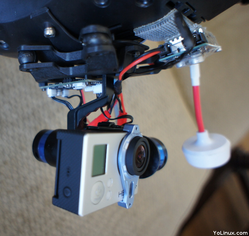
GoPro Camera Gimbal: Tarot (front view)
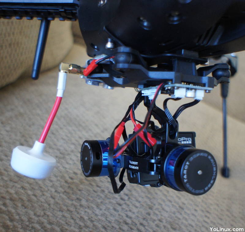
GoPro Camera Gimbal: Tarot (rear view)
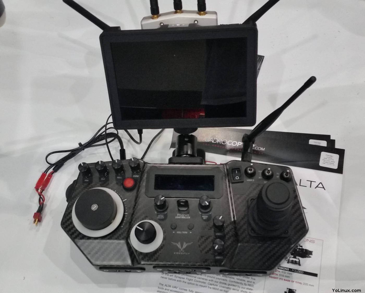
FreeFly Movi camera gimbal remote control
Most consumer drone gimbals are controlled via a knob on the flight transmitter to tilt the gimbal up or down. Left/Right control is up to the vehicle yaw control to turn the drone either way. Professional video is controlled by a separate video operator which allows the pilot to focus on flying. The "pro" systems often have fully independent and unrestricted 360 Left/Right control, clockwise/counter-clockwise roll as well as up/down tilt and various camera controls like zoom and focus.
Remote Gimbal Controllers:- FreeFly: Movi
- Intuitive Aerial: Dominion
- Shot Over - gimbals and controllers for large pro cinema video cameras
Typically the video TX/RX is on 5.8 GHz. The transmitters typically have a USB Mini-B plug to the video camera. A RP-SMA (Reverse Polarity - Sub-Miniature Version A) antenna is connected using coaxial RF connectors.
Frequency: Specialty FPV video transmission systems are available on 900 Mhz, 1.3 GHz and 2.3-2.4 Ghz ferequencies frequencies. See RMRC: Ready Made RC
- 5.8 GHz: Most common video transmission frequency. Does not require a licence if compliant with FCC part 15. Many channels (32), small antennas and poor range. To avoid interference, stay 2 channels from neighboring pilots.
- 2.3GHz/2.4GHz: Intermediate to long range. Interferes with typical RC radio (same frequency).
- 1.3 GHz: long range systems. Larger antennas often limit use on small drones.
- 900 MHz: Long range but close to cell phone frequency and high potential for interference.
Analog vs Digital: Analog is often preferred for its zero-latency transmission. This is essential for FPV racing and anyone flying by video. Analog video is more susceptible to interference and will pick up adjacent channels if in close proximity. Digital HD transmission exists and is of higher quality but has a noticeable latency.
Video Transmitter/Receiver Systems:
- Amimon - Connex wireless HD TX/RX video links
- Ares
- Immersion RC
- Teradek - professional high-end systems
Video Transmitters: (typically range from 25 mW to 60 mW)
- FlySight TX - 200 mW - 600 mW
- Tactic FPV - TX
- Intuitive Aerial: high end large camera gimbal and integrated video gimbal controller
- Paralinx.net - real-time wireless HD transmission. Can multi-cast to up to four receivers. Antennas. - pro quality
- Lumenier - fixed and adjustable RF power
- RMRC: Ready Made RC
Video Receivers:
- IfTronTech: Clearview professional grade receivers
- RMRC: Ready Made RC
- Tactic - display and FPV goggles
- Display Screen Receivers:
- TacticRC (RX also have wrist watch display)
- FlightSight
- Lilliput
- Goggles:
- Fat Shark - RX goggles and TX camera
- Cinemizer OLED
- HeadPlay (large and high res)
- Zeiss VR One - goggle frame of iPhone. DJI compatible with the CloudLight FPV iPhone app.
- Vuzix
- SpektrumRC: Fat Shark Teleporter - RX goggles and TX camera
- Yuneec: Skyview
- Epson: Moverio augented reality
Accessories:
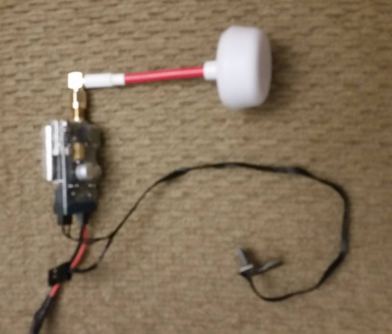
The black pigtail connects to the camera (in this case a GoPro), and the black/red pig tail connects to a power supply. Antenna is shown connected to the video transmitter. The antenna is an omni-directional cloverleaf design. Note that cloverleaf antennas can be "Left-Hand Circular Polarized" (LHCP) or "Right-Hand Circular Polarized" (RHCP). Both the video transmitter and receiver should have the same polarization. A regular stick antenna has Linear polarization. Also see the FPV Video antenna guide.
Channel Frequencies (5.8 Ghz band, 32 channels):
| Channel Number | Group 1 | Group 2 | Group 3 | Group 4 | Group 5 | Group 6 | Group 7 | Group 8 |
|---|---|---|---|---|---|---|---|---|
| A | 5.865 | 5.845 | 5.825 | 5.805 | 5.785 | 5.765 | 5.745 | 5.725 |
| B | 5.733 | 5.752 | 5.771 | 5.790 | 5.809 | 5.828 | 5.847 | 5.886 |
| E | 5.705 | 5.685 | 5.665 | 5.645 | 5.885 | 5.905 | 5.925 | 5.945 |
| F | 5.740 | 5.760 | 5.780 | 5.800 | 5.820 | 5.840 | 5.860 | 5.880 |
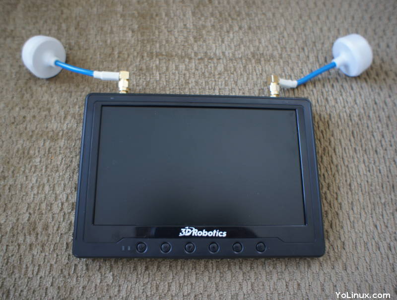
FlySight Black Pearl (3DR IRIS Video RX): 5.8 GHz video receiver and 7" display.
Transmitter video mount - 3D printed (Phoenix Flight Gear)
Video Mounts:
- 3DR Iris Transmitter phone mount
From Thingiverse.com, a source for 3D printed custom parts for mounts and drone accessories.
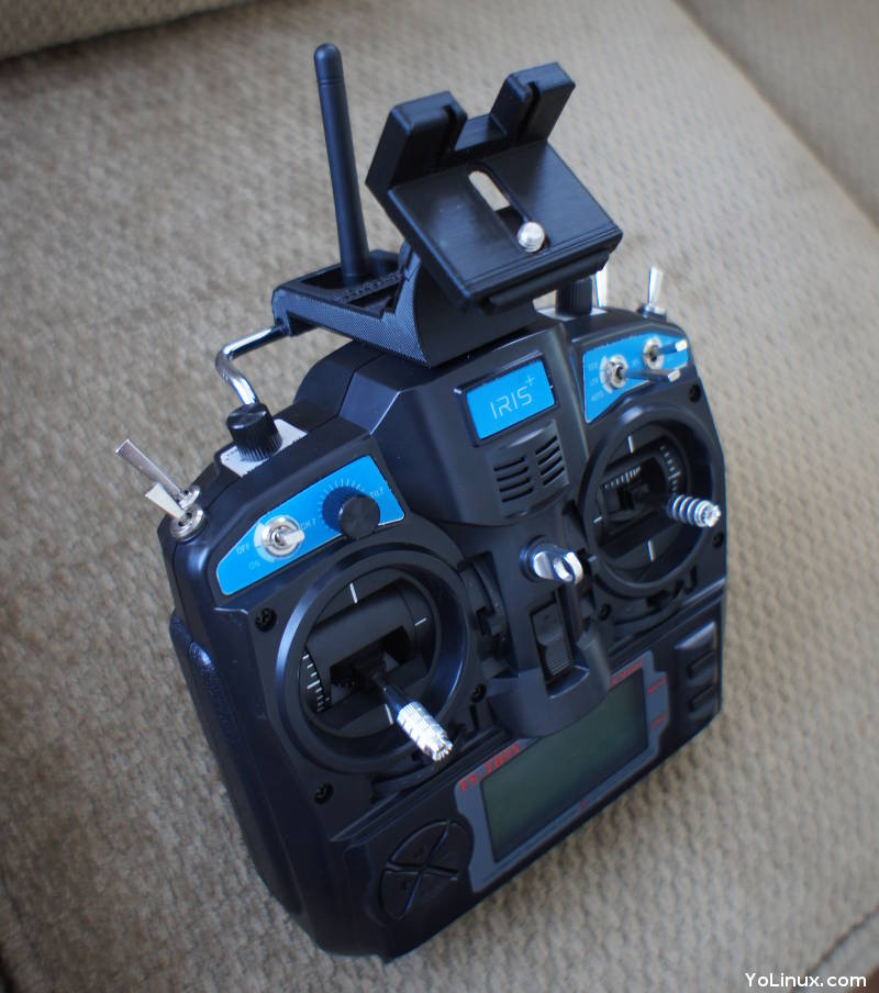
Typical consumer drones operate on an unlicensed frequency band (FCC title 47 part 15) at 2.4 GHz (2.4055-2.475GHz range) and provide 8 or more control channels. The transmitter and receiver use spread spectrum Automatic Frequency Hopping Digital System (AFHDS) to avoid narrow band interference (interferance on one particular frequency). The FCC also permits more power to be used on spread spectrum systems than on fixed frequency bands (one Watt vs 100 milliwatt per FCC part 15).
Left joystick:
- Up/Down: Throttle to make the drone go up or down
- Left/Right: yaw (spin counter clockwise/clockwise)
- Up/Down: Forward/backward flight also known as pitch
- Left/Right: fly left/right also known as roll
Switches and knobs control specific functions such as camera pitch, pre-programmed functions such as Return to Launch (RTL), etc. The screen in the lower middle is a telemetry display.
The standard RC Receiver outputs a Pulse Width Modulation (PWM) signal. The typical flight controller (Pixhawk) will be designed to accept a Pulse Position Modulation (PPM) signal and will require a PPM encoder to translate PWM to PPM. Some receivers have been designed for use with drone flight controllers and will output a flight controller ready PPM signal. PWM uses a separate wire for each signal (parallel) while PPM sends all signals over a single wire (serial bus: SBUS). There are other protocols now available such as FrSky IBUS (digital protocol) and Digital System Multiplexer (DSM) introduced by Spektrum. For more see RC protocols explained. Also note that if you buy the transmitter and receiver separately, you will have to "bind" the receiver to the transmitter so they communicate.
- Futaba
- SpektrumRC
- Graupner
- JR Americas
- Turnigy
- RadioLink
- TacticRC
- Chaney Aerospace: Ranger Drone transmitter
- Yuneec: Ground Station transmitters - integrated RC, telemetry and video
- Esprit Carbon TX - programmable
- Qsrccn Hobbies - USB connected Transmitter Simulator
PPM Encoders: convert PWM (one wire per channel) standard RC receiver output to PPM (single wire) for input to the flight controller. For more information see PPM Encoders
- Channel 1: Roll
- Channel 2: Pitch
- Channel 3: Throttle
- Channel 4: Yaw
- Channel 5: ...
The RC transmitter firmware is typically proprietary but hackers have dived into this code as well:
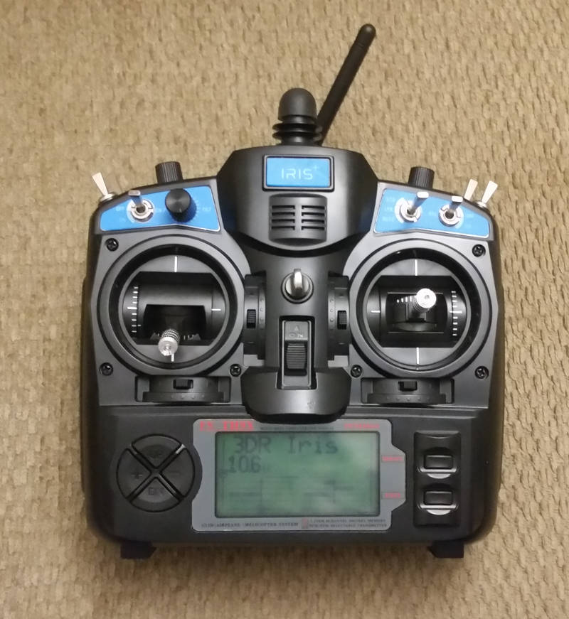
3DR FM radio Transmitter (FlySky FS-TH9x PCM1024 eight channel PCM/PPM selectable)
Provides Gaussian Frequency Shift Keying (GFSK) modulation (how digital data is transmitted), voltage warning for less than 9 volts (typically 12 volts), 2.4 GHz AFHDS.
PCM: digital (unpredictable if mixed between brands), supports error correction and failsafe modes. Better in radio noisey environments.
PPM: analog (can mix between brands), radio noisey environments can generate eratic behavior.
- BMS - long range video/data transmission 1km to 200+ km
- ItElite: 5 GHz - extended range video antennas
ItEDBS - DJI and racing extenders, Video (5GHz) and RC (2.4 GHz) transmitter range extending antennas to double or triple the normal range. - Scherrer UHF - long range systems
- Turnigy long range module - JR UHF and Chainlink UHF Ham band TX/RX 2 to 60 km range
Typically the multi-copter drones are electric powered using 11 to 15 volt (depending on the manufacturer) lithium-ion polymer batteries, also known as LiPO batteries. These batteries use a semi-solid polymer gel electrolyte instead of a liquid one. They are also charged in a Nomex burn proof pouch in case they catch fire while charging. The charger must also be careful not to over-charge the battery or exceed its charging rate to avoid over-temperature conditions. Overcharging can result in a slight vaporization of the electrolyte resulting in de-lamination of the cells and diminished reliability.
Balance Connector: There is typically an extra pair of wires connecting the battery to the charger known as the "balance connector" which helps to monitor and "balance" the charge among the cells in the battery. Without the balance connector, an imbalance can occur which could lead to cell damage or in extreme cases, result in a fire. The charging wire connects to the positive of one cell while the negative connects to one cell at the other end of the series of connected cells. For a typical 11.1 volt battery of three cells, the voltages are additive in series: 3.7v, 7.4v and 11.1 v. A single cell should never be charged beyond 4.2 v as damage and fire may occur. Only the balance connector will be connected to each cell in the series. The balancer can monitor and even discharge the higher voltage cells before they become problematic. There are three popular balance connector types:
- TP: Thunder Power (2 mm spacing)
- JST-XH (0.1 in spacing) [most popular]
- Hyperion (0.1 in spacing)
Dangers:
- Never charge a battery that is at a temperature below 0ºC (freezing) as you risk an explosion at these temperatures.
- Cells that are obviously swollen or have physical damage should never be used. A swollen cell should never be punctured.
- If the battery is getting hot, unplug it! This can lead to a swollen cell.
- Only charge a LiPO battery in a fireproof container.
- Never leave a LiPO battery charging unattended.
- Never allow a single cell to discharge below 3.3 v for a 3.7 v battery. If the cell ever reaches 3.0 volts or lower, it is done, never use it again. This may sound strange when compared to NiCad or automotive batteries. Always store a LiPO battery charged (3.8 v) to avoid a low voltage condition.
- A LiPO battery cell MUST stay within a voltage range of 3.0 to 4.2 volts to avoid damage to the battery. The electronic speed control (ESC) will have a low voltage cutoff (LVC) programmed to 3.0 volts to prevent an over-discharge condition. In flight there will be a sudden drop in power caused by the LVC.
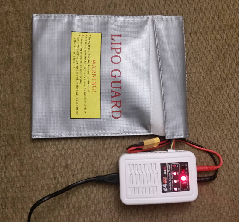
LiPO batteries require a "Constant Current/Constant Voltage" (CC/CV) charging system. A LiPO compatible charger also keeps the current constant until the battery reaches its peak voltage.
LiPO Balance Chargers:
- Duratrax
- Dynamiterc
- ElectriFly
- EV-Peak
- Graupner - small to industrial
- HiTec RCD
- iCharger
- iSDT - battery chargers and checkers
- Progressive RC - portable charging cases
- Pro Tek
- RadioLink - charge six batteries at a time
- Spard Battery
- Thunder Power
- Turnigy
- Venom Power
Lithium Polymer (LiPO) batteries are used in drones because of their low weight compared to NiCad, NiMH and lead-acid batteries, have a high energy to weight ratio and offer high discharge rates. Typically they are good for 400 to 500 recharge cycles.
HV: High-voltage packs can be charged up to 4.35 Volts rather than to the standard 4.20 Volts for the standard LiPO battery packs. HV LiPO batteries deliver more capacity while maintaining the same lifespan. This is accomplished with a silicon-graphene material which protects the anode at the higher voltage.
C Ratings: Lithium Polymer batteries have a "C" rating to describe their "capacity" for discharge or continuous discharge rate. Charging is typically at a "1 C" rate. The burst rate is typically twice the continuous discharge rate but can not be sustained. Higher "C" rated batteries also suffer less from voltage drops under load as they have the capacity to deliver more energy.
Single Cell Charging Capacity:
| Percent Charged | Voltage |
|---|---|
| 100% | 4.20v |
| 76% | 4.03v |
| 52% | 3.86v |
| 42% | 3.80v |
| 30% | 3.79v |
| 11% | 3.70v |
| 0% | 3.60v |
Drone Battery Vendors:
- LiPO Batteries:
- Dynamiterc
- Duratrax
- E-flite
- ElectriFly
- FlightPower
- GenAce - German batteries
- Graupner
- Lumenier - with graphene for higher energy density
- Max Amps
- Pro Tek
- Shida Battery Technology Co
- Spard Battery
- Tattu
- Turnigy
- Venom Power
- Vigor Power Battery Co
- H2 Fuel Cells:
- EnergyOr - 1790 Watt hrs at 310 Watts, extended duration
- HESS Energy Systems
- Intelligent Energy - Hydrogen Fuel Cells for extended flight
FlightWave Drones - drone with H2 fuel cell - 2 hr flight time - MMC (Shenzhen, China)
- Protonex
Battery Meters/Balancers: measure voltage in each cell and option to balance
Power Accessories:
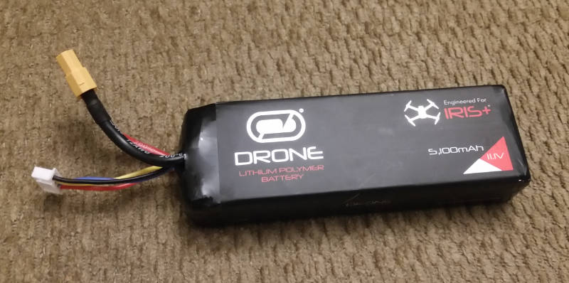
Venom LiPO 5100 mAh, 11.1 volt 3S 8C battery for the IRIS+
- Discharge rate: 8C (5.1 A x 8 = 40.8 A max continuous discharge rate)
- Number of Cells in Series: 3 S (3 x 3.7v cells in series = 11.1 volts)
- Operational Voltage: Low: 10.5 V, Max: 12.6 V
- Power connector: XT60
- Balance connector: JST-XH
- Weight: 320 g
- Dimensions: 13.5 cm x 4 cm x 2.5 cm
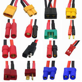
Battery Connectors:
- Amass - battery connectors
Drones typically use electric brushless motors where the RPMs are controlled by the frequency of the pulses to each phase rather than by voltage. Brushless electric motors output more torque, are nearly free of vibration and respond extremely quickly compared to internal combution engines. The brushless electric motors are able to apply speed corrections many times a second, a characteristic required for attitude adjustment. One electric motor rating you will see printed on the side of a brushless drone motor is the "Constant Velocity" or Kv rating. This is NOT kilo volts but the number of revolutions per minute (RPM) at one volt under no load. For example a 920 kV motor running a 11.1 volt LiPO battery would have a free spinning RPM of 920 x 11.1 = 10,212 RPM. Drone motors are designed to provide more torque by increasing the windings of a thinner wire with more volts but fewer amps which will typically also reduce its kV RPMS and turn a larger propeller. A motor designed for higher kV RPMs will typically have fewer windings of a thicker wire that carry more amps but fewer volts and turn a smaller propeller. Racing drones will be designed to use higher RPM motors and a smaller prop while the heavy lift multi-rotor drone will be equipped with high torque motors and a larger prop. See this guide to motor selection.
Electric:
- KDE Direct: motors, ESC, propellers - light to heavy lift motors
Build a system web app - calculate power, weight, motor and prop sizing - MontoRC.com - Avroto, motors, ESC and prop kits
- HiTec RCD - motors and ESC
- T-Motor - heavy lift motors, ESC and props
- Turnigy - motors, ESC, chargers, batteries
(available from HobbyKing: Turnigy MultStar Motors) - Castle Creations
- Lumenier - FPV racer motors
- E-Flite - motors, ESC, batteries
Internal Combustion:
- SkyFront - hybrid
- Top Flight - hybrid
- Unmanned Systems Source - source for drone components (Tucson AZ)
- Lumenier - components to complete a drone
(prop thrust graphs) - Gryphon - graphite composite air-frames and parts (Korea)
- XM2 - graphite composite parts (Gryphon)
- FrtCarbon - carbon fiber tubes, frames, sheets, rods
- Carbon Core
- KDE Direct - propellers and adapters
- Tarot - frames, props, gyros, electronics and parts
- Dragon Plate Products
- China Carbon Fiber
- Mark Forged - carbon 3D printing. 3DR IRIS+ arms
- TC Model - air frames, motor brackets, folding joints and arms, and parts
- APC Propellers
- Master Airscrew - propellers
- T-Motor - foldable carbon fiber propellers
Open Designs:
- Dassault Systemes:
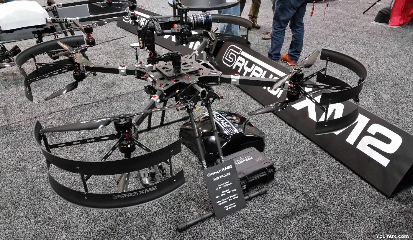
Gryphon XM2 X8 Plus
- Parazero: drone parachutes - for ASTM 3322-18 compliance
- Dubro: Prop balancer
- Trackimo: GPS + cellular tech - track, locate and recover drone
- Sensirion: Airspeed Sensor
- HFE International - deicing and UAV internal combustion engines
- EarTec - wireless headsets
- Maxx Mod - 3D printed accessories
Travel Cases:
Travel even by car or SUV can be difficult without a travel case. Note that soft backpacks are protective from all sides except from the top and thus are not generally suitable for shipping a drone or for airline travel.
- GPC - Go Professional Cases
- Aerial Media Pros - cases and backpacks
- Custom Case Group: Drone Hangar - Hard and soft customized cases
- Fuerte Cases
- Microraptor - soft and hard cases
- LowePro - backpacks
- Nanuk
- Pelican Cases - generic cases (you customize)
- Wingtote
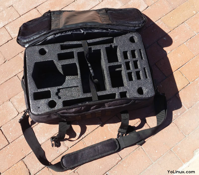
Microraptor backpack for the 3DR IRIS
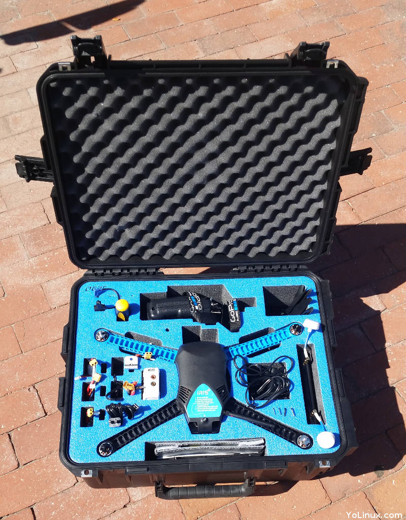
CGP hardened travel case for the 3DR IRIS
- FAA NOTAM website - NOtice To AirMen
- FAA TFR list - Temporary Flight Restrictions
- SkyVector - NOTAMs and DROTAMs (Drone Notice To AirMen)
- 1800wxBrief - FAA Flight Service - airport frequencies, NAVAIDS, NOTAMS, weather, etc
- AMA - Academy of Model Aeronautics, Advocates and insurance
- AOPA.org - Aircraft Owners and Pilots Association. Non-profit political organization that advocates for general aviation.
- Cabezon Group - UAS operating procedures and administration consulting services
- Cyclops Technologies Inc - drone consulting services
- Drone Compiler - cloud logging solutions, compliance, training and professional Services
- Gowdy Brothers Aerospace - UAS consulting, FAA 333 exemptions, training, ...
- POMS and Associates - expertise in insurance and risk management
- UAV Systems Association (UAVSA) - legal services, training services, representation. The Association supports commercial and recreational owners to fly safe and in secure environments.
- Unmanned Risk - Insurance
- Trade Shows/Conferences:
- International Drone Expo (IDE)
- UAS Summit and Expo
- NAB Show - Media, Entertainment and Technology
- AUVSI's XPonential - all things unmanned
- UAS Summit and Expo
- Drones By Zagora - the Commercial Applications for Unmanned Aerial Vehicles (UAVs) Conference
- DAR: Drone Aviation Radar
- Index of drone companies and services
- YoLinux list of "Structure From Motion" solutions - generate 3D models from aerial photos
- Federal Aviation Administration (FAA) Advisory Cirular 91-57 "Model Aircraft Operating Standards"
Drone must be less than 55 lbs, fly at least 5 miles from airport (or notify/negotiate with airport traffic control), obey Temporary Flight Restrictions (TFR), Notices to Airmen (NOTAMS) and Prohibited Flight Space, fly less than 400 feet above ground level (AGL), etc - FAA Part 107 [pdf] - Summary Of Small Unmanned Aircraft Rule
- Temporary Flight Restriction (TFR)
- Notices to Airman (NOTAMS)
- FAA: Unmanned Aircraft Systems (UAS) - information
- KnowBeforeYouFly.com - Drone information portal, air space maps (no fly zones), etc
- NCSL: National Conference of State Legislature
- FCC Title 47
Civil Aviation Airspace Classifications:
- Class A: airspace at 18,000 feet above sea level (MSL) and above
- Class B: airspace used by the highest classification of airports. There are 37 class B airports in the US including Chicago O'Hare, Atlanta and New York La Guardia.
- Class C: smaller than B but have a control tower and a radar-controlled approach system. Regular commercial passenger jet service. Examples include Chicago Midway, Sacremento CA
- Class D: functioning control tower but not for commercial flights. Cylindrical airspace from the surface to 2,500 feet AGL
- Class E: airspace begins at ground to 700 ft AGL and 1200 feet AGL to 18,000 feet above MSL. Not a conflict for drone operators at less than 400 feet.
- Class G: non-controlled airspace. Airspace typically used by drones.
| Acronym | Description |
|---|---|
| AFHDS | Automatic Frequency Hopping Digital System - protocol used by flight control RC transmitter and receiver |
| AGL | Above Ground Level |
| AHRS | Attitude and Heading Reference System - used for navigation |
| AOI | Asynchronous Input/Output |
| BEC | Battery Eliminating Circuit (ESC power delivery) |
| CAN bus | Controller Area Network bus standard for micro-controllers and devices to communicate with each other in applications without a host computer |
| CC | Companion Computer (typically a real-time flight "companion" computer connected to a Raspberry Pi) |
| CCD | Charge-Coupled Device - the digital camera image sensor |
| COA | Certificate Of Authorization waiver - a request for a waiver can be granted to allow for flight operation in violation of a TFR. eg for news agencies |
| DSM | Digital System Multiplexer - Spektrum digital receiver protocol used to the flight controller. Also DSM2 and DSMX (newer and improved) |
| ESC | Electronic Speed Controller (controls the rotational speed of the electric motors) |
| FAA | Federal Aviation Administration |
| FLIR | Forward Looking InfraRed |
| FOSS | Free Open Source Software |
| FPV | First Person View |
| GCS | Ground Control Station |
| GFSK | Gaussian Frequency Shift Keying |
| GNSS | Global Navigation Satellite System (using GPS, GLONASS, Galileo or BeiDou systems) |
| HAL | Hardware Abstraction Layer |
| HAT | Hardware Attached on Top (companion processor), also Height Above Terrain |
| HDMI | High-Definition Multimedia Interface (video interface) |
| IMU | Inertial Measurement Unit - orientation and acceleration |
| INS | Inertial Navigation System (used where GPS is blocked/shadowed or has multi-path errors) |
| LOC | Loss Of Communications - failure to transmit/receive to control the vehicle |
| LVC | Low Voltage Cutoff (set by the ESC to avoid battery discharge below 3 v) |
| LWIR | Long Wave Infra Red |
| MIPI | Mobile Industry Processor Interface (VGA camera interface) |
| MRU | Motion Reference Unit |
| MSL | Mean Sea Level |
| NOTAMS | Notices to Airmen - alerts of potential hazards along a flight path. They are issued in an abbreviated format and need to be decoded. See FAA NOTAM website |
| OSD | On Screen Display |
| OTG | On The Go USB port for a device to act as a host |
| PCM | Pulse Code Modulation - digital protocol for RC receiver to communicate with the flight controller. Less popular than PPM |
| PDB | Power Distribution Board - motor power connection to battery link |
| POSIX | Portable Operating System Interface: Unix based family of standards specified by IEEE for operating system compatibility |
| PPM | Pulse Position Modulation - protocol for RC receiver to communicate with the flight controller. Single wire |
| PWM | Pulse Width Modulation - protocol for RC receiver to communicate with the flight controller. One wire for each signal line. Eight channel receiver requires eight wires |
| RC | Radio Control - the flight control transmitter/receiver |
| RF | Radio Frequency |
| RMS | Root Mean Square - arithmetic mean of the squares of a set of numbers. RMS voltage is a measure of typical generalized voltage |
| ROS | Robot Operating System - middle-ware layer and support apps which run on Linux or a POSIX compliant OS |
| RPM | Rotations Per Minute |
| RTF | Ready To Fly |
| RTL | Return To Launch - an automated failsafe mode to return the drone to the launch point. GPS assisted |
| RTOS | Real-Time Operating System (code runs on processor without sharing with multiple users and applications which reduce the latency and predictability of the software's response time) |
| RX | Receiver |
| SBUS | Serial Bus: signal protocol where instead of running separate signals on separate wires, all signals are sent on a single wire using a protocl to multiplex the independent signals |
| SUAS | Small Unmanned Aerial Systems |
| TFR | Temporary Flight Restrictions - a type of NOTAM that temporarily restricts certain aircraft from operating within a defined area. Defines area, effective period, altitudes affected, FAA coordinating facility and contact number, reason for TFR, etc. Example events: sporting events, US presidential visit. See FAA TFR list. Can counter with a COA. |
| TITA | Time In The Air |
| TX | transmitter |
| UAS | Unmanned Aerial Systems |
| UAV | Unmanned Aerial Vehicle |
| UTM | UAV Traffic Management (a NASA program to manage flight paths) [UTM Interest Website] |
| UBEC | Universal Battery Eliminator Circuit |
| VGA | Video Graphics Array |
 Books:
 |
"Multi-rotor Platform Based UAV Systems"
(1st Edition) by Franck Cazaurang, Kelly Cohen, Manish Kumar Sams Publishing, ISBN# 1785482513 (Jan 16, 2012)
|

|